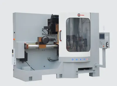
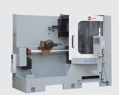
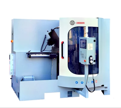
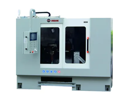
JX350 Face and top grinding machine(Robotic arm)
Basic Attributes
- Blade Outside diameter 120-350 mm
- Package size 2350*1850*2260 mm
- Machine Size 2250*1700*2100 mm
- Total power 4.2 kW
- Coolant tank capacity 120 L
- Grinding wheel linear speed 28 mm
- Grinding wheel outside dia. 125 mm
- Grinding speed 0.5~6 mm/s
- Bevel grinding top&face 45 °
- Clearance Angle 6-45 °
- Rake angle -5~40 °
- Tooth Pitch 7-60 mm
- Max blade thickness 10 mm
- Bore hole diameter 20-60 mm
- Machine Weight 1,900 kg
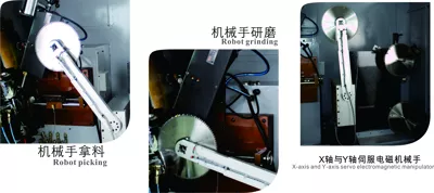
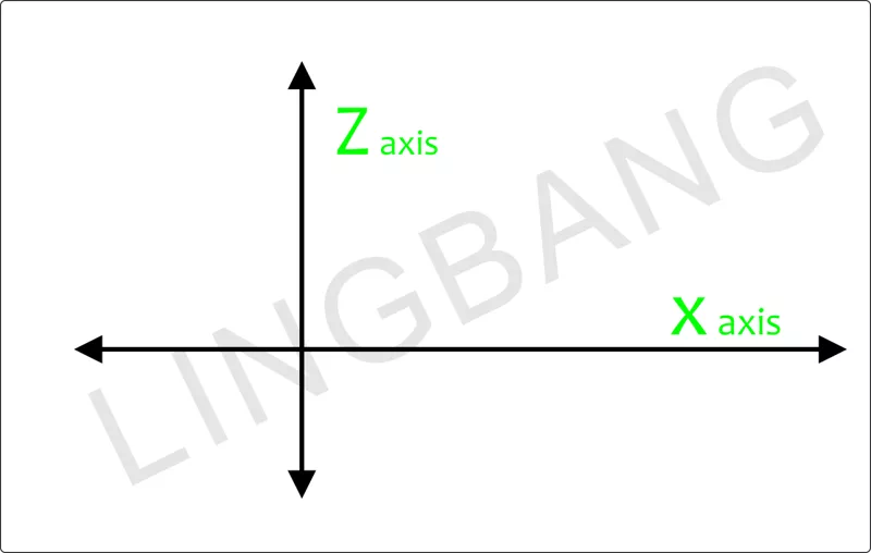
The high-precision servo mechanical hand is composed of the X axis, Y axis, and servo planetary motor.
The high-precision servo mechanical hand has four working positions: grinding position (position where the saw blade is being ground), finished product position (position where the saw blade is placed after grinding), waiting position (position where the mechanical arm is waiting while the main machine is operating).
Mechanical hand adjustment operation process:
1. Use the high-precision servo to rotate the mechanical arm and align it with the center hole of the material taking position. Then, the Z-axis of the mechanical hand moves back and forth (controlled by a stepper motor) to the saw blade position. The touch screen is used to activate the electromagnet, causing the saw blade to be adsorbed onto the electromagnet of the mechanical arm. Save each coordinate.
2. Adjust the Z-axis to move the saw blade away to the zero position of the Z-axis.
3. Rotate the mechanical arm to move the mechanical part to the grinding position, and then adjust the X-axis of the mechanical hand (moving left and right) to align the center hole of the saw blade with the core sleeve. Save each coordinate.
4. Adjust the Z-axis of the mechanical hand to bring the saw blade close to the position of clamping the carbide sheet. Save each coordinate.
5. The mechanical arm adsorbs the saw blade and moves out of the grinding position, then rotates the swing arm to the feeding position. Align the center hole of the saw blade and the feeding rod to be concentric. Adjust the Z-axis stroke. Save each coordinate.
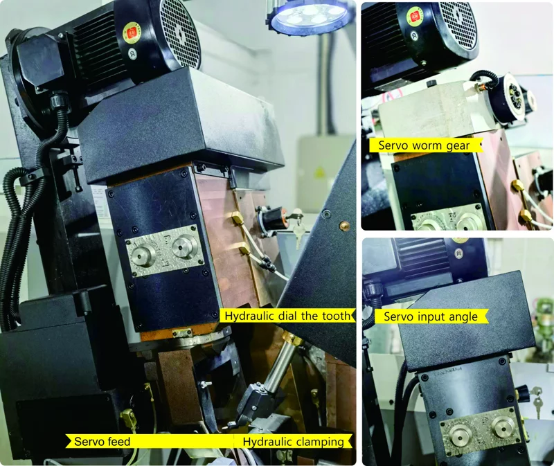
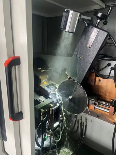
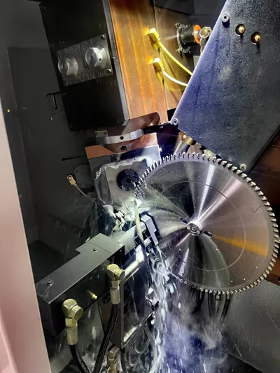
Hydraulic Dial the tooth //Hydraulic clamping//Servo feed
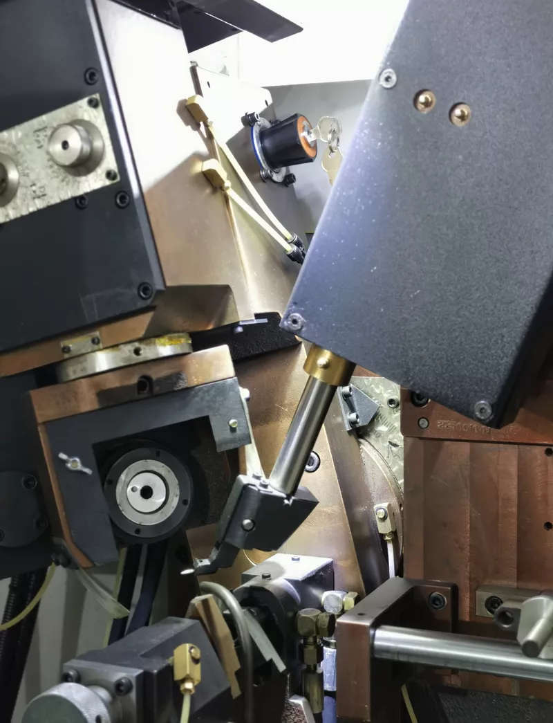
3.1 The actual grinding amount can be accurately controlled through the servo feed system and fine adjustment with the handwheel, with each feed being controlled within 0.01mm. The high-strength hydraulic clamping and tooth-picking system ensure the accuracy of tooth picking and the tightness of saw blade clamping
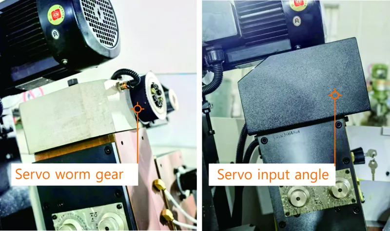
Servo Worm Gear Servo input angle
3.2 The servo motor-driven turbine worm system allows for angle adjustment (direct input available), ensuring stability and precision in maintaining the accuracy of the swing angle.
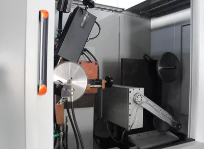
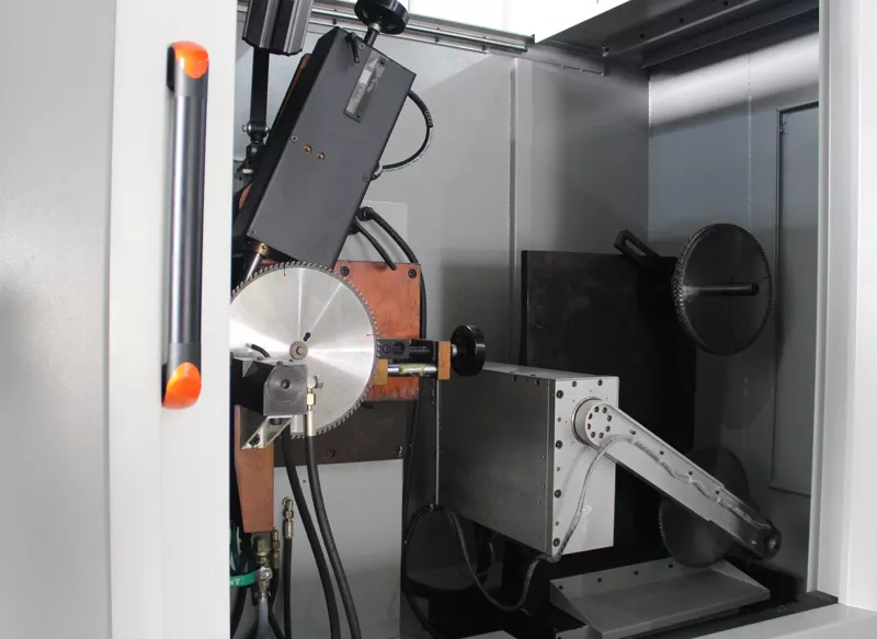
Top grinder
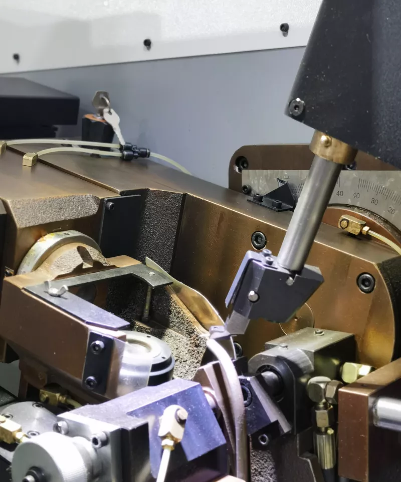
Face grinder
3.3 This machine integrates tooth top and tooth face grinding, requiring only the replacement of the grinding wheel.
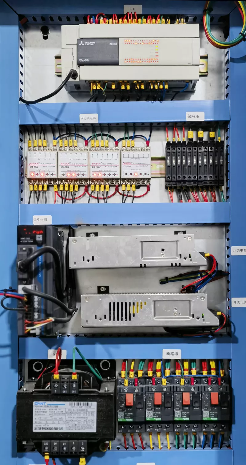
4. Stable control system
4.1 Adopting Mitsubishi PLC control system, Schneider low-voltage management system, and high-stability electrical components determine the overall stability and durability of the system.
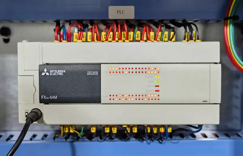
Mitsubishi PLC
5. Body features:
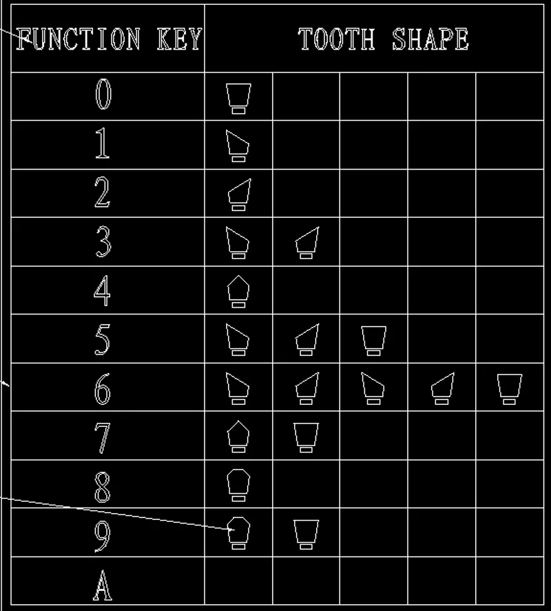
A variety of tooth types can be ground and formed at one time, and the tooth types can be saved and edited as needed.